Refueler
Well-known member
Is that really necessary?
Considering the rubbish posted - why not ??
Is that really necessary?
It maybe rubbish to you, but there are possibly a few reading this that aren't engaging, some are learning possibly, I imagine many teachers possibly feel/say the same under their breath, but would be dismissed if they were to express it.Considering the rubbish posted - why not ??
Exactly - I am explaining the cause of similar symptoms in my own set up. Not in any way saying that applies here or that other solutions are wrong.It maybe rubbish to you, but there are possibly a few reading this that aren't engaging, some are learning possibly, I imagine many teachers possibly feel/say the same under their breath, but would be dismissed if they were to express it.
bedouin is trying to explain how he sees a possibility of a fault, he is not suggesting for one moment it is the fault.
You are entitled to say and write what you like within the rules, I accept that.
Exactly - I am explaining the cause of similar symptoms in my own set up. Not in any way saying that applies here or that other solutions are wrong.
What is shocking is the number of people who can't understand what I am talking about and are absent any understanding of the basics of electrical circuits. So they are trying to tell me that I can't have seen what I see every time I start my engine. There is a certain arrogance in that don't you think?
No Paul has missed the point. I have made it perfectly clear (#15 [see also #17, #34,#37, #62]) the situation I am talking about only applies if there are elements of the wiring of the circuits in common (e.g. the example in #66) and that is the post Paul erroneously contradicts. Paul later comes up with a counter example of a circuit that does NOT have any wiring in common so of course my comments don't apply in that case.Maybe arrogance - but its based on your stubborness to not appreciate that the two circuits are sufficiently separated by not having common +ve - to be acting as indepedent circuits and your voltage drop cannot affect the other circuit.
No Paul has missed the point. I have made it perfectly clear (#15 [see also #17, #34,#37, #62]) the situation I am talking about only applies if there are elements of the wiring of the circuits in common (e.g. the example in #66) and that is the post Paul erroneously contradicts. Paul later comes up with a counter example of a circuit that does NOT have any wiring in common so of course my comments don't apply in that case.
And we have no idea about the details of the OPs circuit.
If you can see anything I have written that isn't 100% correct please point it out.

This is the system that we've been discussing and is what the OP has, he has clearly stated so in his early posts. I have also explained how it is and even provided you with a schematic.That is a different circuit because there is no element that carries both the domestic and starting current and in that case there would be no drop in the domestic circuit.
I have stated my comments only apply where there are wires in common as in the sketch in #66 that we were discussing.
It is not clear to me whether this is the case for the OP - I read that initially as having some element of shared -ve cabling hence my comments
No Paul has missed the point. I have made it perfectly clear (#15 [see also #17, #34,#37, #62]) the situation I am talking about only applies if there are elements of the wiring of the circuits in common (e.g. the example in #66) and that is the post Paul erroneously contradicts. Paul later comes up with a counter example of a circuit that does NOT have any wiring in common so of course my comments don't apply in that case.
Yes we do, he has clearly stated that all negatives are connected together, positives are on separate switches and he has a VSR, exactly the same as my schematic.And we have no idea about the details of the OPs circuit.
Too many errors and lack of understanding to even begin pointing them out.If you can see anything I have written that isn't 100% correct please point it out.
No - there is a significant difference. Your schematic shows all the negative coming to a common point - but no (significant) amount of wiring in common. #66 shows a wire carrying common current between the two circuits.- it is the voltage drop across that wire than causes the drop in the domesticMy schematic has all negatives connected together but not the positives, exactly the same as the sketch it #66
Yes we do, he has clearly stated that all negatives are connected together, positives are on separate switches and he has a VSR, exactly the same as my schematic.
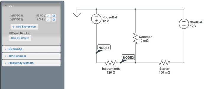
Well there you go...What this simulation shows is that the voltage of the ground side of the house load does rise significantly with respect to the ground of the house battery at the battery (1.092 V) and consequently the voltage across the house load drops.
Yes - and that is what is frightening meI do this as a day job and i also have a boat myself.
Funny, when people can't grasp something they usually resort to taking the piss.Yes - and that is what is frightening me
From post #1I have not seen any post from the OP that says whether or not any -ve wiring is in common, which is why I have stressed so repeated what you seem to have missed - that this is only an issue when there is.
post 66 was for simplification as you well know.No - there is a significant difference. Your schematic shows all the negative coming to a common point - but no (significant) amount of wiring in common. #66 shows a wire carrying common current between the two circuits.- it is the voltage drop across that wire than causes the drop in the domestic
I have repeated said my comments only apply when there is common wiring like that - but no need for any commonality in the +ve
#106 gives concrete figures that prove what I have been saying.
I have not seen any post from the OP that says whether or not any -ve wiring is in common, which is why I have stressed so repeated what you seem to have missed - that this is only an issue when there is.

Have you not read the original post#1 ? where the OP clearly states that the batteries have a common ground and describes the boat as being wired exactly as per Paul's diagram with the exception of having solar feeding into the VSR. His problem has been solved many, many posts ago - or at least the principles of what to look for with specific reference to the VSR. The simplest solution to eliminate the VSR as an issue is to connect the solar direct to the house bank which is the one that needs it most.I have not seen any post from the OP that says whether or not any -ve wiring is in common, which is why I have stressed so repeated what you seem to have missed - that this is only an issue when there is.
Well done sir for sticking to your guns. I knew that you were correct because I made exactly the same conclusion many posts ago but then the usual arrogant always right posters stepped in and I stepped back as I do not have the patience to argue with these know it alls who are sometimes very wrong.Yes - and that is what is frightening me
Do you have any research to back up this claim?Well done sir for sticking to your guns. I knew that you were correct because I made exactly the same conclusion many posts ago but then the usual arrogant always right posters stepped in and I stepped back as I do not have the patience to argue with these know it alls who are sometimes very wrong.
Any common cable in the negative connections to both batteries will cause the negative in one battery to rise to a slightly positive voltage with respect to the junction of the negatives thereby reducing the voltage available.
Sam.
Do you have any research to back up this claim?
If it was possible what sort of voltage change would cause the chart plotter to turn itself off and on again? I know mine is good down to 10.4 volts, I've tested it and once it is off it is off.
Ah - you have seen the light - a new wire has magically appeared and now there is no common wire in the circuits that there clearly was in #66.post 66 was for simplification as you well know.
The reality is boats are wired to their individual negatives and the negatives are connected.
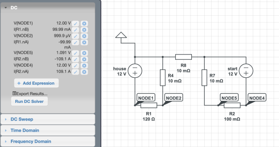
so just for fun here is what it looks like with a shared neg but individual returns on each circuit:
View attachment 174703