Instruments turn off when starting engine having added extra battery,

PaulRainbow

Well-known member
Joined
16 May 2016
Messages
15,887
Location
Suffolk
Visit site
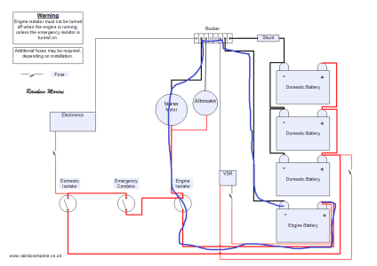
It is the negative arrangement in this diagram that I think some have in mind rather than the earlier one. Ie a shared cable rather than parallel. 2 circuits sharing a common -ve wire. Certainly this is the arrangement on my boat (not the +ve side though - I am not talking about that).
The negative arrange in my schematic is the same as the OPs, as is the positive arrangement, that is what he has said and it's the most common arrangement on the planet (for boats).
So, what would you see in terms of voltage drop at both the individual loads if there was a poor connection in the 'to all negatives' line when you turn the engine over, assuming the +ve sides are separate? Would you see a voltage drop in both circuits? It's hard to see how you wouldn't as you can't have 2 potential differences for the same wire. If so, would it be more apparent when you turn the engine over and you put a big load down it?
To get a voltage drop you need a circuit, as there is no positive connection there is no circuit and a voltage drop on the domestic systems is impossible. A circuit consists of a positive and a negative connection. You cannot have current going from the domestic negative to the battery negative without the positives being connected, surely you know this ?

Do we know what the -ve arrangement is for the OP - I cannot see it? How do you know it isn't this one as so many seem to?
As above, the OP states that the negatives are connected but the positives are separate circuits with their own isolator switches, therefore he has the same circuits as in the diagram i posted.
 

bedouin

Well-known member
Joined
16 May 2001
Messages
32,342
Visit site
To get a voltage drop you need a circuit, as there is no positive connection there is no circuit and a voltage drop on the domestic systems is impossible. A circuit consists of a positive and a negative connection. You cannot have current going from the domestic negative to the battery negative without the positives being connected, surely you know this ?
If you don't have a circuit the engine won't start. If you do have a circuit current flows and there is a potential difference across the wires.

A couple of people on this thread have suggested removing the starter battery in order to fix the problem!!!!! How on earth they think the engine will start like that I have no idea - perhaps they intend to hand start it.
 

PaulRainbow

Well-known member
Joined
16 May 2016
Messages
15,887
Location
Suffolk
Visit site
How can these two circuits run at different voltages when they share a wire? Does that wire know where the electrons came from and run down a different lane like a motorway?
All of the circuits in your house share a neutral. Normally, all of the lives are the same voltage. If the circuit breaker on the cooker panel trips that circuit is at 0v but all of the others are still at 240v.

Same on your boat, if the engine battery is flat that circuit is at 0v, the domestics are still at 12v.
 

Buck Turgidson

Well-known member
Joined
10 Apr 2012
Messages
3,191
Location
Zürich
Visit site
If you don't have a circuit the engine won't start. If you do have a circuit current flows and there is a potential difference across the wires.

A couple of people on this thread have suggested removing the starter battery in order to fix the problem!!!!! How on earth they think the engine will start like that I have no idea - perhaps they intend to hand start it.
who has suggested removing the starter battery to fix the problem? please quote the post!
 

PaulRainbow

Well-known member
Joined
16 May 2016
Messages
15,887
Location
Suffolk
Visit site
If you don't have a circuit the engine won't start. If you do have a circuit current flows and there is a potential difference across the wires.
You have a circuit for the engine and a circuit for the domestics, see my schematic above. That's two separate circuits with a common negative. There is no connection between the two positives, so current cannot flow between the two circuits, therefore voltage drop on one circuit does not effect the other.

Not sure why you cannot grasp the simple fact that current cannot flow along a single wire, there needs to be a circuit.
 

Sandy

Well-known member
Joined
31 Aug 2011
Messages
20,942
Location
On the Celtic Fringe
duckduckgo.com
If you don't have a circuit the engine won't start. If you do have a circuit current flows and there is a potential difference across the wires.

A couple of people on this thread have suggested removing the starter battery in order to fix the problem!!!!! How on earth they think the engine will start like that I have no idea - perhaps they intend to hand start it.
May I suggest a large mug of coffee. ;)

You can have two separate circuits with a common negative (or ground); the clue is in the name. With boats it is a starter circuit connecting the starter battery to the starter motor and a house circuit from the house battery to things like lights, chart plotters and fridges.

Another example of common ground is a motor vehicle where the whole metal structure is connected to the negative and the positive is heavily covered in a non-conductive material and led to where you need an electrical current then plugged in.

Sometimes we get clever and add a VSR into the positive side where when the voltage is more than 13.XX volts it closes and power can flow into two circuits. As soon as it drops to less than 13.XX volts it opens and isolates the second circuit, in my case that is the house batteries. If the OP has this set up then there should be no voltage drop on the house side of things.
 

PaulRainbow

Well-known member
Joined
16 May 2016
Messages
15,887
Location
Suffolk
Visit site
You are confusing current and voltage.

The vertical line in the middle is shared between both. There is voltage drop across that wire that is equal in both circuits.
Don't be ridiculous, how can the domestic circuit voltage drop when there is only a negative connection ? The voltage drop only exists in the engine circuit, because of the current flow, there is no current flowing in the domestic circuit so there will be no voltage drop.
 

Pye_End

Well-known member
Joined
5 Feb 2006
Messages
5,075
Location
N Kent Coast
Visit site
As above, the OP states that the negatives are connected but the positives are separate circuits with their own isolator switches, therefore he has the same circuits as in the diagram i posted.
Which diagram - you posted two which are quite different, and both have connected -ve's, but one has a shared -ve.
 

bedouin

Well-known member
Joined
16 May 2001
Messages
32,342
Visit site
Don't be ridiculous, how can the domestic circuit voltage drop when there is only a negative connection ? The voltage drop only exists in the engine circuit, because of the current flow, there is no current flowing in the domestic circuit so there will be no voltage drop.
1) Is there or is there not a voltage drop across that wire?

2) Is that wire or is it not part of both domestic and starter circuits?

If the answer to 1 and 2 is yes then there is a voltage drop in both circuits.
 

PaulRainbow

Well-known member
Joined
16 May 2016
Messages
15,887
Location
Suffolk
Visit site
1) Is there or is there not a voltage drop across that wire?
There is a voltage drop on the starter circuit
2) Is that wire or is it not part of both domestic and starter circuits?
It is not. Part of it is part of the start circuit, part of it is part of the domestic circuit. The only time it is part of both circuits is if/when the two positive connections are in parallel.
If the answer to 1 and 2 is yes then there is a voltage drop in both circuits.
The answers are not yes, there is no voltage drop in both circuits, just the one with the current draw.

In the schematic below i have roughly sketched the engine circuit. The blue line is that circuit and current is flowing around it through the starter motor. You can see, the current does not flow through the rest of the negative wiring, as there is no path for it to do so, the domestic positive is not part of the same circuit. Therefore, there can be no voltage drop in the domestic circuit.

Charging-2-banks-VSR.png
 
Last edited:

Refueler

Well-known member
Joined
13 Sep 2008
Messages
17,818
Location
Far away from hooray henrys
Visit site
He would say your instruments wouldn't work at all and you wouldn't be able to turn over your engine.

But the point is the domestic circuit is not connected to power the starter ... so as far as the starter is concerned - only having a common -ve is an open circuit as there is no +ve connected to starter circuit from the domestic ...

Its not Ohms Law as Ohms Law does not cover an open circuit .....
 

Refueler

Well-known member
Joined
13 Sep 2008
Messages
17,818
Location
Far away from hooray henrys
Visit site
If you don't have a circuit the engine won't start. If you do have a circuit current flows and there is a potential difference across the wires.

A couple of people on this thread have suggested removing the starter battery in order to fix the problem!!!!! How on earth they think the engine will start like that I have no idea - perhaps they intend to hand start it.

This is the first post of yours that actually starts to show any understanding of a circuit ... pity about the other posts !!
 

B27

Well-known member
Joined
26 Jul 2023
Messages
1,244
Visit site
You are confusing current and voltage.

The vertical line in the middle is shared between both. There is voltage drop across that wire that is equal in both circuits.

Redraw the diagram with that wire replaced by a resistor and it might make more sense to you
This.
Basic mesh theory of circuits.
For 'resistor' read 'impedance' perhaps, it might be inductive....
 
Last edited:

bedouin

Well-known member
Joined
16 May 2001
Messages
32,342
Visit site
There is a voltage drop on the starter circuit

In the schematic below i have roughly sketched the engine circuit. The blue line is that circuit and current is flowing around it through the starter motor. You can see, the current does not flow through the rest of the negative wiring, as there is no path for it to do so, the domestic positive is not part of the same circuit. Therefore, there can be no voltage drop in the domestic circuit.

View attachment 174692
That is a different circuit because there is no element that carries both the domestic and starting current and in that case there would be no drop in the domestic circuit.

I have stated my comments only apply where there are wires in common as in the sketch in #66 that we were discussing.

It is not clear to me whether this is the case for the OP - I read that initially as having some element of shared -ve cabling hence my comments
 

B27

Well-known member
Joined
26 Jul 2023
Messages
1,244
Visit site
...

How on Earth do you get a positive spike when the positives are separate ?
V=-LdI/dT dI/dT, that's a big negative number when the starter current is stopped instantly.
Vehicle electrics are very dirty

'Earth'! ISWYDT :)

I'd guess the answer is more mundane though.
VSR closed, or has some AC path perhaps?
Some other link between the two circuits.
If those are ruled out, you may need to look at the 'unlikely' things, maybe try a choke or filter on the plotter supply.
May be worth powering the plotter from a little 12V battery to check the problem goes away? If not it has to be the data lines?
Methodically rule things out.
 

B27

Well-known member
Joined
26 Jul 2023
Messages
1,244
Visit site
All of the circuits in your house share a neutral. Normally, all of the lives are the same voltage. If the circuit breaker on the cooker panel trips that circuit is at 0v but all of the others are still at 240v.

Same on your boat, if the engine battery is flat that circuit is at 0v, the domestics are still at 12v.
Not much of the neutral is shared.
Each circuit takes its own neutral wire from the neutral connection of the RCCB.
Where you have two RCCBs or a protected and non-protected section of the consumer unit, the 'neutrals' are distinct circuit nodes, or the RCCBs would trip all the time.
 

Refueler

Well-known member
Joined
13 Sep 2008
Messages
17,818
Location
Far away from hooray henrys
Visit site
I had a dedicated engine start battery and two 60AH service batteries. Each battery has its own switch.

As two 60 AH batteries is too little I have added two 110V batteries making the house battery capacity 340 Ah.

Engine battery is separate with its own seitch, but all neutrals 0V are connected.

There is a VSR for charging and the service batteries are joined as one bank. The only change I believe that I have made, is that there are now extra batteries and the +ve is taken from one end of the bank and the -Ve as at the other end which I believe is correct, Where as previously it was +ve and -ve of the house batteries was connected to one battery and the second battery was connected +to + and -to - This I believe not to be best practice.

What is likely to cause the instruments (plotter) to restart on engine start?

Is it poor -Ve connection?
VSR?

I thought I had just increased the house battery capacity.

TIA

Just to get the thread back on track ...

It is quite obvious that there is an error in setup .... maybe VSR is closing because of Solar ... maybe a cable has been connected to wrong bank ... etc etc.

But please - the rubbish about a -ve cable and voltage drop ???
 
Top